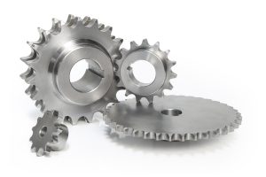
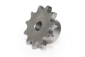
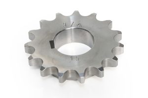
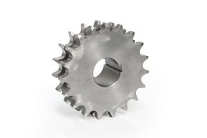
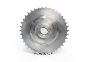
A sprocket is a mechanism for transmitting power by winding a chain onto gears or pulleys. The sprocket system works by meshing one or more sprocket pulleys to a chain. This system is often used in applications that require high power transmission capacity.
Chain mechanisms are considered as an intermediate mechanism between gearwheel and belt pulley mechanisms. It creates an advantage to transmit power and motion over long distances.
CHAIN GEAR CALCULATIONS AND GENERAL TOLERANCES
DIN 8187 ISO/ 606
t : Step
Z : Number of Teeth
da : Diameter Above Tooth
do :Section Circle Diameter
df :Tooth bottom diameter
ds : Friction Diameter
D :Spool Diameter
dgmax : Maximum Hub Diameter (Intermediate Diameter)
n : ‘n’ Value for Departmental Apartment
q : Value of ‘q’ for Tooth Bottom Inspection
B1 , B2 , B3 , b1 :Tooth Thickness
W :Chain Intermediate Width
k :Number of Times for Maximum Hub Diameter
C :Tooth Cheek Radius
MRC, MRT : Pin Top Control (number of teeth even/odd)
MDC,MDT :Tooth Bottom Control (number of teeth even/single)
Ce : Distance Between Sprocket Axes
CL :Distance Between Axes Most Suitable for the Found Chain
Z1,Z2 :Number of Teeth (Large/Small)
L links :Total number of chain links (chain length)
CHAIN GEAR CALCULATIONS AND GENERAL TOLERANCES
DIN 8187 ISO/R 606
Tooth bottom diameter: h11
Diameter over thread: +/-3mm
Thread thickness: h14
Hole diameter(dm) : H8
Hub diameter(dg):+/-3mm
Hole-tooth axial misalignment :0.0008.df+(0.08 or 0.15) max misalignment = 0.76mm
Lateral Wobble:0.0009.df+0.08 max wobble=1.14mm (Welded Hub)
Overall Thickness (A):+/-1mm (+/-2mm for welded cores)
*TS 1845 and TS 1980 tolerance standards are used in the manufacturing of all our products.


